This is the documentation for the 2016 competition robot built by FIRST Robotics Competition Team #2655, The Flying Platypi. The code is built in LabVIEW and contains many features including:
- An integrated script interpreter built into the driver station that:
- can interpret CSV files on the driver station PC and sends them to the robot at the beginning of a match
- is interpreted in the autonomous LabVIEW code and executed in the order specified in the CSV file
- A control scheme built for tank drive controlled with a PlayStation 2 controller
- Talon SRXs used in a Master-Slave speed feedback configuration to provide the driver with precise control
- A “Drive Straight” function implemented to aid in crossing defenses during teleop
- An IMU and a Gyro/Accel board supported in the code and swappable by a single boolean in Robot Main .vi
Feel free to clone/fork the project and take a look around! Every effort has been made to keep the code as modular as possible. If you have any questions, open a request! IMU code was integrated from the official ADIS16448 RoboRIO Driver repository.
Autonomous
Autonomous Routines
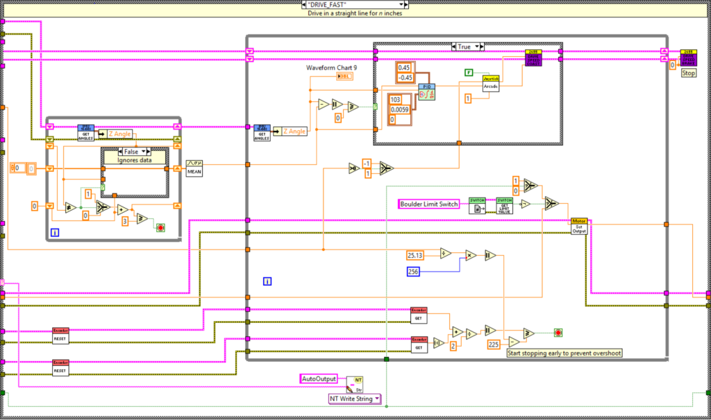
This year our team decided to run our Autonomous routines based on an array of strings and an array of numbers that would control the Autonomous routines. In the Autonomous Independent.vi a For Loop runs for as many iterations as there are commands in the array of strings that makes up the array. Then each string in the array of strings is fed into a Case Structure and it will run each function. The argument from the array of strings is read and used in each function as it is needed. For example, in the DRIVE_SLOW function the argument is the number of inches the robot will move and in the ROTATE_TO function the argument is the number of degrees.
Autonomous Scripting
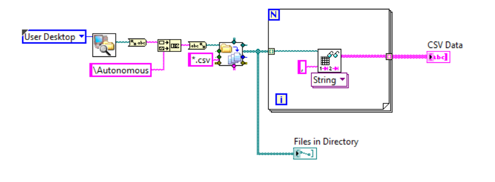
For creating Autonomous routines we made a system to make it easy enough for anyone to create a routine. To do this, we made an Autonomous Scripting program in Java. The Autonomous Scripting program write a routine to a text file by pressing buttons. This script can be read in the Dashboard code using the Array Parser.vi and the CSV Parsing.vi. CSV Parsing is used to read all of the information from the .csv file and the Array Parser is used to convert this information to an array that can be used as a routine. This array is then sent to the robot using the Array to Autonomous Commands.vi. Here they are sent to the robot and used to select the functions to run.


Autonomous Functions
For each function of the robot there is a function that is selected in the code using the case structure. Each of these cases has an input, known as the argument, that is used wherever it is needed within the case.
WAIT
This function is used to make the robot wait a specified number of seconds which is determined by the argument.
STOP
This case stops all of the drive motors, the ball intake motor, and retracts both the Defense Destroyer and the ball intake. There is no argument required for this function. This is only used at the end of a routine.
RESET_GYRO
This executes the 16448 reset function within the IMU code. This has no argument and should always be used at the beginning of each Autonomous routine.
ROTATE_TO
This case uses a PID loop to tune rotation of the robot. It will run until the Z angle of the IMU is within half a degree of the argument.
DRIVE_FAST
This case is used to drive forward at full speed until it reaches the length specified by the argument, which should be measured in degrees. It has a PID loop on the rotation so it should drive in a straight line.
DRIVE_SLOW
This case is used to drive forward at 70%l speed until it reaches the length specified by the argument, which should be measured in degrees. It has a PID loop on the rotation so it should drive in a straight line.
BALL_INTAKE_DOWN
This function lowers the ball intake system. If the limit switch is not pressed it will also start the boulder intake motor. This requires no argument. This function does not run for a specified time so it is recommended to follow it with WAIT so that the ball intake system has time to lower fully.
DEFENSE_DESTROYER_DOWN
This lowers the Defense Destroyer. It requires no argument. This function does not run for a specified time so it is recommended to follow it with WAIT so that the Defense Destroyer has time to lower fully.
DEFENSE_DESTROYER_UP
This raises the Defense Destroyer. It requires no argument. This function does not run for a specified time so it is recommended to follow it with WAIT so that the Defense Destroyer has time to raise fully.
BALL_INTAKE_UP
This function raises the ball intake system. If it is running, the boulder intake motor is stopped. This requires no argument. This function does not run for a specified time so it is recommended to follow it with WAIT so that the ball intake system has time to raise fully.
BALL_OUT
This sets the boulder motor to release the boulder. No argument required.This function does not run for a specified time so it is recommended to follow it with WAIT so that the ball has time to eject fully.
BALL_STOP
This function stops the boulder intake motor. No argument is required.
CAMERA_ALIGN
This function automatically aligns the robot using the camera.
Dashboard
Log Path
The Log Path.vi is used in getting a file reference that is later used in the Datalogging.vi. This .vi gets a timestamp of the time a match started in the form of a date string and a time string. These strings are then concatenated with an underscore between them. Then, all of the characters that are not compatible with file names are replaced with periods or underscores. After this this timestamp string is concatenated with the reference to a folder named Logs and “.txt” is added on the end. Then this is converted from a string into a file reference, which is created using the Open/Replace/Create File.

Datalogging
Another .vi we made was the Datalogging.vi. This is used to track motor current, battery voltage, gyro values, and IMU values all throughout the match. It uses the file reference outputted from the Log Path.vi and uses it to write a delimited spreadsheet. It takes the array of data from the motor current, battery voltage, gyro values, and IMU values and appends it to the text file once every second using a comma as the delimiter.

Gyro Crossover
The Gyro Crossover.vi is used to make a visual interface possible for the driver when using indicators on the dashboard. It takes the gyro value and if it is greater than zero it will check to see if it is greater than 360 degrees. If it is not it will pass the value through to be used as the gyro value. If it is it will be divided by 360 using the Quotient & Remainder function to see how many times the gyro value is divisible by 360 to result in a whole number. It will then multiply this whole number by 360 and subtract this value from the original value to get an output. If the gyro value is less than zero the same logic will be used. Instead of checking to see if the input is greater than 360 it will check to see if the input is less than -360. If this is false it will add 360 to the gyro value to get the final output.

Encoder Crossover
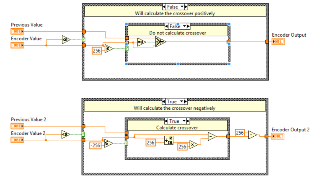
The Encoder Crossover.vi is similar to the Gyro Crossover.vi. It serves to create a visual interface in the driver station using indicators. If the encoder value is greater than 0 it will check to see if it is divisible by 256. If it is not the value will be passed through. If it is it will be divided by 256 using the Quotient & Remainder function to see how many times the encoder value is divisible by 256 to result in a whole number. It will then multiply this whole number by 256 and subtract this value from the original value to get an output. If the encoder value is less than zero the same logic will be used. Instead of checking to see if the input is greater than 256 it will check to see if the input is less than -256. If this is false it will add 256 to the encoder value to get the final output. This function is repeated twice for the two encoders.
IMU to Normal Gyro
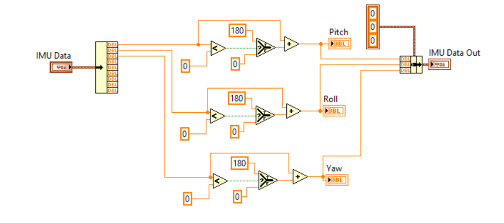
The IMUtoNormalGyro.vi is used to convert the IMU data to that of a normal gyro. The IMU goes on a scale of -180 to 180, so if pitch, roll, and yaw are less than 0 180 will be added to them. This makes sure that the values will be on a scale of 0-360 so that they can be used as ordinary gyro values.
Teleop
Straight Line Drive
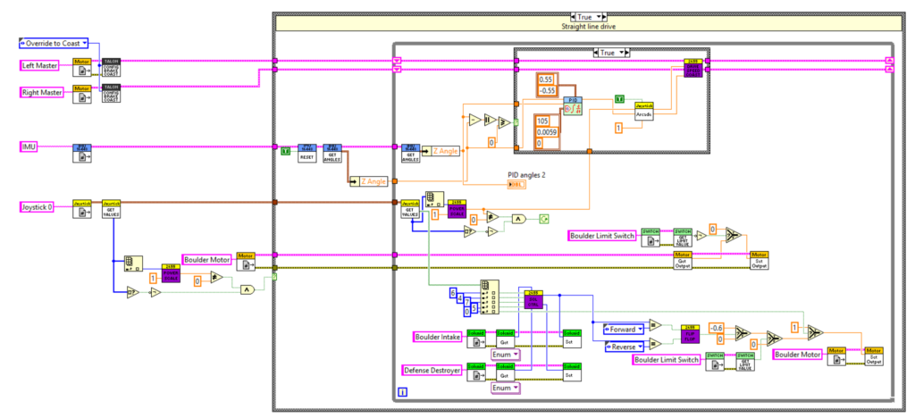
In Tele-Op the driver can also use our straight line drive function. This can be used to keep the robot moving in a straight line even if it is crossing over an obstacle or is being hit by other robots. It moves at a constant speed forwards or backwards whenever a one of the POV buttons is pressed and uses a PID to adjust the direction that it moves based on the gyro.
Drive Talons
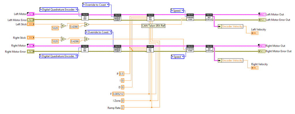
The Drive Talons Coast.vi controls the drive motors. It sets the motors to use the encoders on the robot. We can use this to have the robot compensate for any drift while driving and still drive in a straight line. We also set them to Override to Coast mode, which allows the motors to ramp down instead of immediately stopping the robot as soon as there are no joystick values present. Another thing we do is set the PID on the controller as well as the ramp rate.We also set the joystick motor values to Speed and Percent VBus. The default values is Speed, but this does not allow the driver to get unstuck on a low battery. When the driver presses the override button on the controller the mode will be changed to Percent VBus to allow this to happen. There is also a similar .vi known as the Drive Talons.vi which sets the mode to Override to Brake instead of Override to Coast.
Solenoid Control
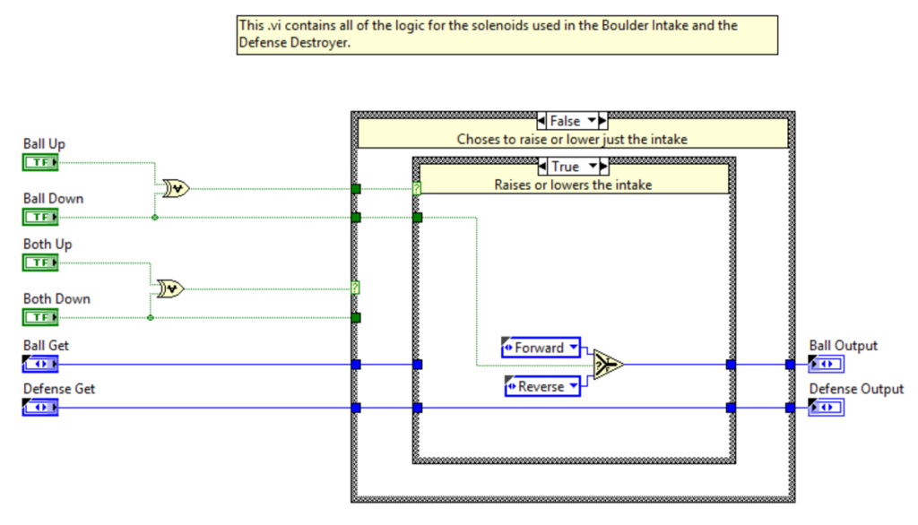
The Solenoid Control.vi has all of the logic used for the solenoids on the Defense Destroyer and the ball intake. It will raise and lower just the ball intake or raise and lower both the ball intake and the Defense Destroyer. This is structured as what would be an flip flop statement in Java. This .vi can either change the output of the solenoids depending on the joystick input or keep it the same as in the previous occurrence.
Autonomous Script Manager
Manager
The autonomous script manager is a java program that creates csv files in a directory on the drive station’s desktop. The csv files are used as autonomous scripts and the relevant columns are sent to the robot as arrays. The script manager allows drivers to write autonomous scripts suited to their needs by clicking buttons and a looking at a table. It allows quicker testing of autonomous as well because there are no changed to the code on the robot side.
CSV Checker
The CSV file checker checks the commands and arguments in a csv file to verify that they are valid. This helps to eliminate simple mistakes in the script that can make the robot not work as intended.
Gyroscope Simulator
The Gyroscope simulator is used to help visualize where the robot will be at any point in the script relative to where it started. This helps drivers and see the absolute position of the robot accounting for gyroscope resets.
